- Worked and led the electronics department in SAE combustion competitions in Germany (2014) and India (2016).
- Development of a wiring harness in several phases meeting project deadlines, measuring lengths, connector types and coupler specifications.
- Calibrating several sensors including the lambda sensor (while engine tuning for closed loop air-fuel ratio control), throttle position sensor (TPS), MAP, crankshaft position sensor, hall effect sensor, thermocouples and coolant temperature sensors for controlling the radiator fan and controlling several other outputs including the fuel pump.
- Developing Arduino circuits, RPM and a gear indicator auxiliary circuits for the information cluster.
- Phase 1: Understanding Input and Output requirements, auxiliary circuits and relay requirements and specifications. Accurate lengths of wires for all sensors and laying the same on a board taking references from the actual vehicle chassis and CAD drawings and software packages taking into consideration packaging constraints, shielding requirements and wire gauge sizes.
- Phase 2: Perform iterations and voltage and current tests along with continuity tests all across the entire wiring harness.
- Phase 3: Using automotive industry grade clips and tubing along the wiring harness and testing it on the vehicle subject to interference and vibration during vehicle handling.
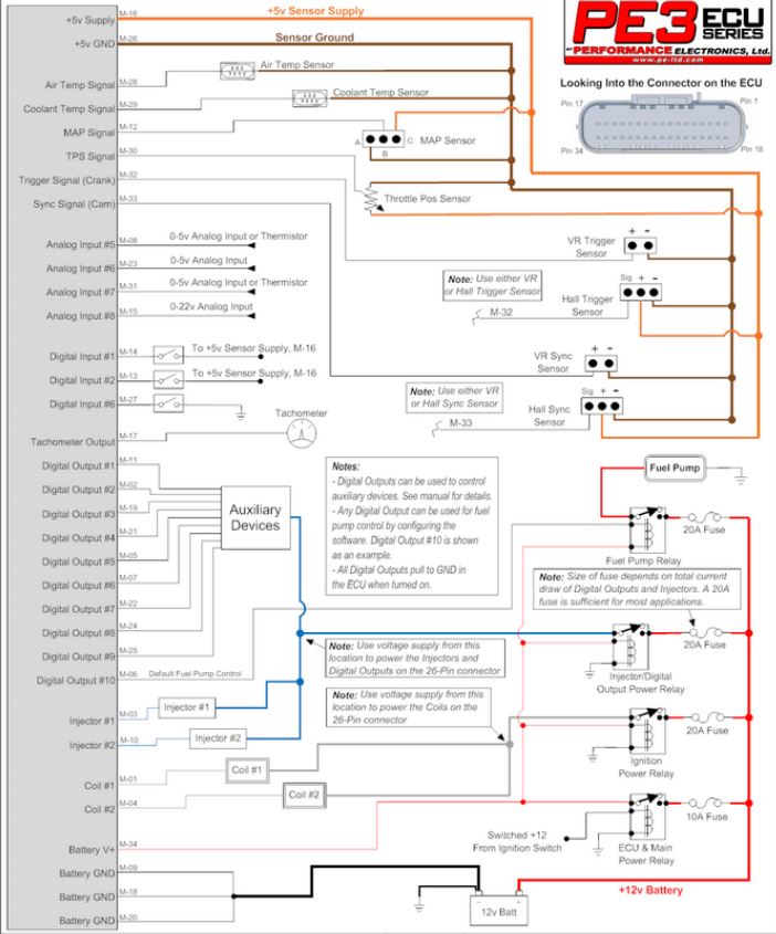
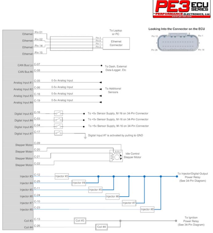
Sample wiring diagrams used with the PE3 ECU are shown below:

Wiring harness: Reference: PE3 ECU

Wiring harness: Reference PE3 ECU